Tuesday, September 25, 2012

My microbot


I bought a Tamiya track set for a robot similar to my lego rover. Once I had used most of it to build those tracks, I had about 4 inches of track, and some of the small wheels left over. I looped the remaining track into two tiny treads and stuck the smallest wheels I had left inside.


They were cute, but soon I realized I could make a drive system small enough for it. I knew people regularly modified servos to turn continuously, and I happened to have a few 7 gram micro servos. Even those would be too wide, but when I got some out and played with them I saw that I could drive the rear cog on one side and the front cog on the other, allowing the two servos to sit offset. I went about modifying the servos. (The tiny resistor pair I used to do it shown below.)


That done, I drilled out the drive wheels to fit the servos, bolted them on, and attached an idler to the opposite side of each with a screw.


Now to power it, I had some cordless phone batteries around, they were each 3.6 volts and I needed about 5, but they were each made for 3 1.2V cells, so I unwrapped and recombined two to make a 4.8V.


Now I had a battery that sat nicely on top, but of course a robot needs a computer, I usually work with pics, but wanting this to be self contained, and shareable, I went with an arduino nano, stuck in a dip socket on top so that I could add accessories, and charge the battery or program the robot with USB.

A zip tie holds it all together, with a cut off bit of eraser between the servos for shock absorption, and it's a robot! I used the servo library to make the control pretty easy. Since the pins stick off the sides adding peripheral involves soldering the wires onto those legs you see sticking out the sides above the battery.

Now to make a swarm of them.


This was an instructables entry last may, it won a prize, see the link if you want details on the build:
http://www.instructables.com/id/Arduino-Nano-based-Microbot/

Saturday, July 7, 2012

My master's thesis


Last month I completed my thesis and graduated with a Master's in Mechanical Engineering from UW-Milwaukee. My thesis was a tactile sensor system for the marine robot LMAR, a mobile platform for scientific experiments, designed to drive into the surf of lake Michigan carrying any sensing or sampling equipment required. The issue I came in to solve is navigational sensing; the water is turbulent and full of mud and crap.

At first I considered some sort of antennas, but those would likely break. A bumper seemed too blunt, but I am an engineer, so I made a highly sensitive bumper. It's shock mounted to move forward and back. I ended up using magnetic displacement sensors, when I first saw them I thought they might be too unreliable due to interference, but when I tested them they proved highly precise and very low noise, plus since they have no moving joints they are easy to waterproof.

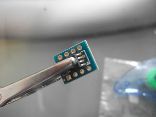
They take the form of a tiny microchip (HMC1501 if you need one). I had to mount it on a breakout board since this project didn't have time for a custom PCB. Since they worked best in a range of about 20 mm I mounted the magnet and chip on beams that would move past each other as the shock absorbers compressed.

I used some plastic I beam that fit directly on to the shock mounting plates. Shown above without springs.

   To back them up I added some simple accelerometers. They are cheap and require no amplifiers, plus they are good at picking up high frequency vibration, though they are not absolute in position, the magnetic sensors have that covered.


The circuit board takes care of power supplies for the logic and amplifiers, as well as reading the analog data and transmitting it to the main computer of LMAR. Besides that I wrote some testing software that plots readouts for debugging. I did that in processing because it was quick. Looking back on it I should have just used labview since it has data logging readily available and that's what they use for the robot itself, which is controlled by a cRIO.


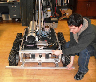
Then of course there was writing the thesis, I won't bore you with the details of that. But it got approved. Here's how the bumper looks on the robot.


Next time, an update about how I made a $20 syma helicopter radio controlled.