Monday, April 7, 2014

My Mini Kossel is operational

I've run the first few test prints on my Kossel Mini 3D printer. It wasn't as difficult to get it running well as I had expected. Some of the choices I made include an Airtripper extruder design,


Modifications
So far I only changed two things from the basic design you can get from github. Most of the links I used, including the supplier for most of the parts are at the bottom of this page (Reprap wiki page for kossel mini). One thing I changed was the carriages. The square peg didn't seem to grip the belt well, so once it was closed using a zip tie it naturally rotated to come off the middle of the peg.

I used this Carriage on Thingiverse by user Pierre233, I added some notches so I could still cinch down the belt plates with a zip tie. My goal was not to eliminate the zip tie, but to put a guide in place to keep the belt straight. I will upload those files with the update when my printer is all finished, since the design could still use some tweaking.

The other change was a machined aluminum print bed, since I want to eventually make it heated. I've countersunk the holes since this picture was taken so that those screws can't get in the way. I'm working on a design to support the bed on an insulating spacer. The screws will still conduct some heat out, but not enough to damage anything or keep the plate from getting warm.

Controller
I went with a Ramps 1.4 board since it is one of the best documented and easy to add things on to. It is running DRV8825 motor drivers, not the more common A4988 ones from pololu. I did this because I want to keep them cool without a fan so I can eventually put the driver board underneath the bed, giving the whole printer a very neat look. This did require adjusting the firmware to use a steps/mm based on a 32 microstep board, A4988 drivers do 16.

The drivers do indeed stay cool. I tuned them to 1.2A, which is what my motors require, the guide to do so is on pololu here (Pololu Driver Page). However the motor squeal is pretty annoying, I've ordered some A4988 drivers to see if it helps. I figure it may be the PWM frequency they use.

Framing
I printed the parts out on a Taz that a friend of mine owns, I didn't have ABS so most of it is PLA. Except for the end effector mount, that might take some heat, and I did have a little bit of pink ABS, so I printed it from that and painted it yellow.

The frame pieces came from Misumi, it saved a little compared to other sources, the total was $42.22. That's 33.12 for the 9 beams 240mm type HFS3-1515 and the 3 beams at 600mm, plus $1.85 tax and $7.25 shipping, and it got here in 4 days. Pretty good.

Movement
For linear rails I searched all over for a salvage source here in the US and eventually had to go through aliexpress. It was $91 and took about a week. They are of nice quality, and for me the extra cost of going with recirculating ball rails is worth it (about $30 more than using v rollers). They look cooler and they are more precise. If I'm going to take the time to build it I figure I'll get the best components I can.

The belts, pulleys, rods and links are all from the same place. (Kossel Parts List)

Hot End
Speaking of quality, the hot end is a J-head straight from the inventor (Hotends.com) since the extruder is the part that seems to fail the most on 3D printers in general I would advise against going with a knock-off to save $30, unless your time is worth less than $3 an hour.


Extruder Drive
I used an Airtripper Bowden extruder (Airtripper files and instructions), I went with rubber hose for the compression as he suggests, and at the Milwaukee Makerspace I found a bearing of the right size, and with a little round groove in it right where the filament needs to go. It works great. When I built it I didn't have the right size tap so I just used a 10-32 screw.

Tuning
I found the information in this blog very helpful (http://minow.blogspot.com/). Basically, you adjust the bed and the endstops to get it level, which you can test by moving equal distances off center and measuring. Then you get the curvature flat, which you measure by going between the center and equal distances from the center and checking the height. For this you will need to adjust the delta radius, which is best adjusted by changing it's inputs. I picked DELTA_SMOOTH_ROD_OFFSET and went through a few cycles of measuring at the middle and 60 mm off center and recording the effect it had. I've gotten a depth gauge but at the time I actually just wrote down how many pieces of paper fit under the nozzle and dialed it in, and it worked fine.


Once you get the curvature down, you can adjust the rod length to get the scale right, I had already measured my rods with a caliper and once the curvature and leveling was done, the first print came out right on scale (see below) so I left that alone.

Full Disclosure, I hunted around a bit to get exactly 25.00mm, it ranged by about 0.07mm. Close enough for me.


This part came out pretty smooth too, I did see a little bit of stranding on the bridges. I've tested it at 0.1mm layer height and haven't had a jam yet, which I'm very happy with since I often see printers having trouble with fine resolution and I had my doubts about pushing the filament through a tube.


Next I'm working on some feet to lift it up a bit, a heated bed and mounts for the control electronics underneath. Also I'll post those carriage files.

Tuesday, September 25, 2012

My microbot


I bought a Tamiya track set for a robot similar to my lego rover. Once I had used most of it to build those tracks, I had about 4 inches of track, and some of the small wheels left over. I looped the remaining track into two tiny treads and stuck the smallest wheels I had left inside.


They were cute, but soon I realized I could make a drive system small enough for it. I knew people regularly modified servos to turn continuously, and I happened to have a few 7 gram micro servos. Even those would be too wide, but when I got some out and played with them I saw that I could drive the rear cog on one side and the front cog on the other, allowing the two servos to sit offset. I went about modifying the servos. (The tiny resistor pair I used to do it shown below.)


That done, I drilled out the drive wheels to fit the servos, bolted them on, and attached an idler to the opposite side of each with a screw.


Now to power it, I had some cordless phone batteries around, they were each 3.6 volts and I needed about 5, but they were each made for 3 1.2V cells, so I unwrapped and recombined two to make a 4.8V.


Now I had a battery that sat nicely on top, but of course a robot needs a computer, I usually work with pics, but wanting this to be self contained, and shareable, I went with an arduino nano, stuck in a dip socket on top so that I could add accessories, and charge the battery or program the robot with USB.

A zip tie holds it all together, with a cut off bit of eraser between the servos for shock absorption, and it's a robot! I used the servo library to make the control pretty easy. Since the pins stick off the sides adding peripheral involves soldering the wires onto those legs you see sticking out the sides above the battery.

Now to make a swarm of them.


This was an instructables entry last may, it won a prize, see the link if you want details on the build:
http://www.instructables.com/id/Arduino-Nano-based-Microbot/

Saturday, July 7, 2012

My master's thesis


Last month I completed my thesis and graduated with a Master's in Mechanical Engineering from UW-Milwaukee. My thesis was a tactile sensor system for the marine robot LMAR, a mobile platform for scientific experiments, designed to drive into the surf of lake Michigan carrying any sensing or sampling equipment required. The issue I came in to solve is navigational sensing; the water is turbulent and full of mud and crap.

At first I considered some sort of antennas, but those would likely break. A bumper seemed too blunt, but I am an engineer, so I made a highly sensitive bumper. It's shock mounted to move forward and back. I ended up using magnetic displacement sensors, when I first saw them I thought they might be too unreliable due to interference, but when I tested them they proved highly precise and very low noise, plus since they have no moving joints they are easy to waterproof.

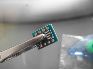
They take the form of a tiny microchip (HMC1501 if you need one). I had to mount it on a breakout board since this project didn't have time for a custom PCB. Since they worked best in a range of about 20 mm I mounted the magnet and chip on beams that would move past each other as the shock absorbers compressed.

I used some plastic I beam that fit directly on to the shock mounting plates. Shown above without springs.

   To back them up I added some simple accelerometers. They are cheap and require no amplifiers, plus they are good at picking up high frequency vibration, though they are not absolute in position, the magnetic sensors have that covered.


The circuit board takes care of power supplies for the logic and amplifiers, as well as reading the analog data and transmitting it to the main computer of LMAR. Besides that I wrote some testing software that plots readouts for debugging. I did that in processing because it was quick. Looking back on it I should have just used labview since it has data logging readily available and that's what they use for the robot itself, which is controlled by a cRIO.


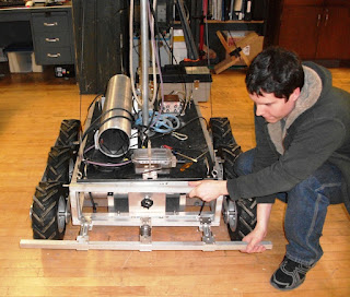
Then of course there was writing the thesis, I won't bore you with the details of that. But it got approved. Here's how the bumper looks on the robot.


Next time, an update about how I made a $20 syma helicopter radio controlled.

Saturday, October 30, 2010

My instructables Halloween contest entry

My latest work:
http://www.instructables.com/id/Cheap-easy-motion-detecting-prop-dropper/Though it's been two months since my last post, that's actually been due to a deluge of projects, not a shortage of them. The cyclic load fatigue tester has been upgraded, both with better control software and a sturdier table. In senior design I'm working with two other students on a Thermoaccoustic engine, I'll post about that when it's further along. In experimentation I've just started on a fluid temprature regulator, a machine that cools or heats water to a desired temperature. Then there's the human powered vehicle, I'm head of the components team and we've just finished the prototype for the front wheel drive/front wheel steering drive train. I'll have picture of this all as it completes. For now, check out my Instructable, and if you have an account there, vote it up.

Saturday, August 14, 2010

The cyclic load fatigue tester

My project for most of the summer has been this cyclic load testing machine. It is an unpaid research project that will earn me some class credit. The idea is to create a machine that can apply a controlled force to bend the bicycle fork back and forth thousands of times, measuring the load and displacement and recording the two. The goal is to find out how well current specifications for bicycle forks, typically made of metal, predict failure in composite forks, such as the one mounted in the machine here.
Most of the electronic equipment is from Enfield, they supplied the PID (green) the servo valve (black just above the pid) and the pneumatic ram with a built in potentiometer to detect position. I fabricated the mounting structure for the ram, and the mount for the head tube was created by another student before I began this project. A PID is a device which outputs a control signal which is intended to control something so that the feedback signal matches the command signal. for example if you used it on an oven the control would control the heating elements, the command would be a signal equivalent to what the temperature sensor would read at the temperature you desired and the sensor would of course be the temperature sensor. In this application I wired the feedback to a load cell (a sensor which detects force) and the control to the servo valve that lets air in and out of the ram. Then I give the PID command signal corresponding to the load cell reading for the amount of force I want, and it adjusts the valve accordingly. To generate the command signal I have a LabJack U3, one of many data acquisition devices available. We chose this one because it is fast, has good sample code in many languages, and includes analog outputs, so we can use it for control as well as recording.
At this stage in the project I have the machine working, and I have figured out the commands to control it from VB or C++ (.NET 2008 versions), so it's mainly a matter of writing the software. There does seem to be an issue with the range on the load cell, but I have others I can try. I just got as far as making the force feedback work with the PID. In general my plan is first make it work, then make it better.

Tuesday, June 29, 2010

The tank drive RC motor driver

I started working with electronics about a year ago. Most of the things I created during that time were simple learning exercises, such as blinking a light with a PIC chip, or with a radio transmitter. Recently I completed the first working build of my first real electronics project. It is a board that interprets the signal from a radio receiver for an RC servo set and generates a corresponding motor power output, two of them actually.

First there was the development of the code, I used a PIC 18F1320. I mainly chose this chip because I had experience with it, and I knew it was just powerful enough without being excessive. Most of the time on this went into making the PWM signal interpretation code. The signal that is output by the servo for the receiver is pulse width modulated, that means it sends pulses of various lengths to the servos to indicate the desired position. For most servos the standard is that a 1 ms pulse is all the way to the left, and 2 ms is all the way to the right, 1.5 being the center. To make it as precise as possible I use the capture module on the chip so that instead of checking the ports on regular intervals, I could have it check the time when the logic level at the port changed. The problem with that is that there is only one CCP (capture, compare and pwm) module on this chip, and I wanted to capture atleast two servo signals.
Eventually I learned that most RC receivers output their signals for each servo with a given space in between, I figured I could use this gap to differentiate between them with just one pin, but that didn't work. Eventually I hooked it up to an oscilloscope and found out why: on my receiver the pulses had no space between them, furthermore if I connected any two adjacent channels to the same pin they shorted out the receiver and the whole thing shut down. Fortunately the two problems can solve each other, since the signals are stacked together, and my receiver has three channels, I can just capture the first and third, and the gap between them is the length of the second. Here's the code I came up with, it's kind of long to re-post here.
After that adding the motor PWM features was fairly easy. I added a button to calibrate the board (turn the transmitter high, press, leave it neutral, press, turn it low, press, so on for the next channel) and two lights to indicate the calibration state.

Next was designing the board, I used an L298n H-bridge chip to amplify my pwm signal to actually power the motors, and drew the whole thing up in eagle. Note the filtering diodes on the signal in, this is to keep the thing from shorting itself out, oddly it usually works without them, but not always.

After that I soldered the prototype board, to my surprise it worked in the first try. My only other practice at circuit board soldering was when I made my Junebug kit to start programming PICs. For that I just watched some youtube videos on how to solder perf boards and I got a 30W soldering iron from sears.


With that made and tested I made some adapter wires using some old lego wires of mine that had come loose. They have pins made from snapable headers at one end and lego plugs at the other, I figured a versatile testing medium for the RC controller would be legos and here is the resulting robot:

just the body

with the driver board and receiver

The next step in this project is a more solid version, I'm working on the schematic to create an actual board. I've built a gearbox, and I plan to make a solid works model for a simple frame, then fabricate it out of aluminum. It will be a bit more compact than the prototype, I've ordered some L293D chips, which are smaller than L298s and drive about half as much current (the dual gearbox uses 800ma motors), they also have built in clamp diodes which should save some space on the board.

For now I'm having fun driving the lego version around, I stuck on the wireless camera and a flashlight and drove it around from the TV like a space probe.

Wednesday, May 26, 2010

The Story So Far

It's time I start keeping some kind of record of all the thing's I make. I'm a creator, I don't claim to be good at everything, but I am good at making things. Some of my projects from the past have no record, but I'll add old ones as I find them. I'm not going to list it all off, it would be better to just show you the old and new projects as I recall and create them. I am a Mechanical Engineering student at UW Milwaukee, I have a welding and fabrication degree which I earned in North Carolina, I've worked as a ranch hand, a welder and an industrial engineer, and freelanced as an artist here and there.

These were our costumes at ECU Halloween 2006, I am not a big sewer, though my mom did teach me how. I designed and created the costume that I'm wearing here. It's actually based off of a pattern for a George Washington costume, the tails and narrow waste worked well. I thought I should include this to show some variety, since at the moment I don't have many pictures but the industrial and electronic stuff. These costumes, along with Kelly and Aaron's march hare and red queen costumes, won the ECU costume contest.

Formula Hybrid 2008, on the NCSU team. This was more fun than I can explain. I was the welder on the team and helped with the frame and built the battery guards and most of the mounting required (that's me on the left in the build picture). We started just six weeks before competition, and took it up to New Hampshire. We finished it in the track side garage, staying up all night and sleeping in a truck was hard, but it was fun. We didn't win anything, but we qualified. And I'm sure they're going to do something great next year. I had to move, so I reluctantly left the NC state team and went to Wisconsin where I transferred to UWM.
Now I'm head fabricator on the UWM ASME's unfortunatly named HPV (human powered vehicle) team. I had a co-op term that interrupted this, but here is a pic of the rolling frame prototype we built up. I may have to limit how much I show of this until competition, for the sake of confidentiality.

I've also recently gotten into electronics. This is a starter project I'm just finishing up, and it will probably be my first full post about a project. It's a RC motor controller, it takes the signal from a RC receiver and will use it to directly control two motors, maybe more. The one shown can only control one. Its using a PIC18F1320 to capture the signal and produce the variable speed motor control signal and a L298 Dual H-Bridge to amplify the chip's output and drive the motor. I'm going to take it to the school lab and use the oscilloscope today to get a better idea of what the timing is of the output from that RC receiver. I've got a program for the chip to interpret many signals at once almost worked out, but I can't get the timing right, so I'm hoping that will help. Once it's all working I'll probably make a little RC tank or a lego motor controller with it.

I respond to comments so ask about anything that interests you.